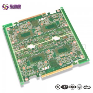
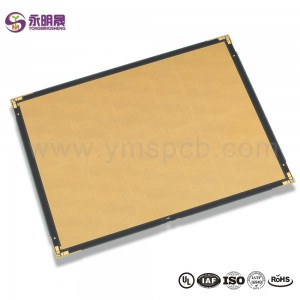
HDI printed circuit boards 8Layer 2 Step HDI Board| YMS PCB
ПХД HDI is the high-density interconnector PCB. It is a type of PCB technology that is very popular in various devices. HDI PCBs are the results of miniaturization of components and semiconductor packages because they can realize more functions on the same or less board area through some technologies.
HDI PCBs have finer lines, minor holes, and higher density than conventional PCBs, providing necessary touting solutions for the chips with many pins in mobile devices and other high-tech products.HDI PCB usually has 4,6,8 layer or even higher.
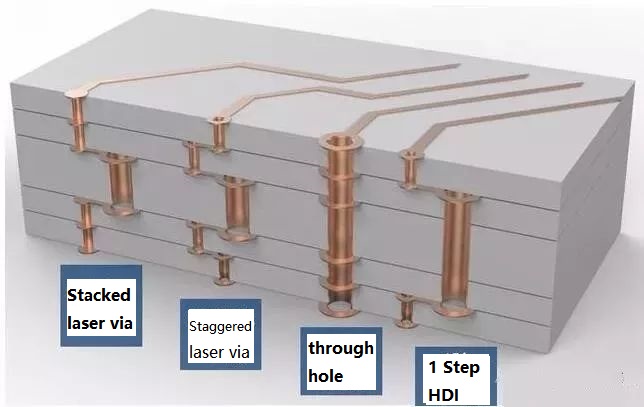
HDI design combines dense component placement and finer circuits, using less board without compromise functions. Compared to ordinary PCBs, the main difference is that HDI PCBs realize the interconnect through blind vias and buried vias instead of through holes. And HDI PCBs use laser drilling while traditional PCBs usually use mechanical drilling. The birth of the HDI PCBs brings more possibilities for portable electronic devices and more challenges for PCB manufacturers. For accommodating the trend of miniaturization and multifunction of electronics, YMS has done a lot to improve the level of equipment and staff professionalism. You can be assured to offer us the HDI designs, and we will give you a satisfactory service and HDI products.
Савет HDI вытворчы працэс:
At present, HDI board interconnection between layer and layer is mainly the following design: Staggered holes interconnection, Cross-layer interconnection, ladder interconnection and superposition holes interconnection. Among them, the superposition holes interconnection occupy the least space. There is a research suggests that reducing the number of through holes and increasing the number of blind holes can effectively improve the wiring density. And in the superposition interconnection, the methods of electroplating and resin plug are mainly used, especially the electroplating hole filling method which has more obvious advantages like high reliability and good conduction performance. Therefore, superposition interconnection is the most widely used design method for blind holes design. The process of stacking between layers is as follows: first blind hole is made, then second blind hole is made after lamination, then multi-blind hole is made according to this method, and the interconnection between layers is realized by electroplating hole filling method.
У цэлым, працэс вытворчасці пліты HDI з'яўляецца комплекс, які павінен быць завершаны пасля таго, як шмат разоў вытворчасці на працягу доўгага часу. Гэта не толькі высокія патрабаванні да дакладнасці і ўсаджванне кантролю кожнага пласта, але і высокія стандарты ў галіне матэрыялаў, абсталявання, аховы навакольнага асяроддзя і тэхнічнага персаналу.
YMS HDI PCB manufacturing capabilities:
| Агляд вытворчых магчымасцей друкаванай платы YMS HDI | |
| Асаблівасць | магчымасці |
| Колькасць слаёў | 4-60л |
| Даступная тэхналогія HDI PCB | 1 + N + 1 |
| 2 + N + 2 | |
| 3 + N + 3 | |
| 4 + N + 4 | |
| 5 + N + 5 | |
| Любы пласт | |
| Таўшчыня | 0,3мм-6мм |
| Мінімальная шырыня і прабел лініі | 0,05 мм / 0,05 мм (2 міль / 2 мілі) |
| BGA КРОК | 0,35 мм |
| Мінімальны памер свідраванага лазера | 0,075 мм (3ніл) |
| Мінімальны памер свердзела | 0,15 мм (6 міль) |
| Суадносіны бакоў для лазернага адтуліны | 0,9: 1 |
| Суадносіны прапорцый скразнага адтуліны | 16: 1 |
| Аздабленне паверхні | HASL, безаланцовы HASL, ENIG, бляшанка для апускання, OSP, срэбра з апусканнем, залаты палец, цвёрдае золата для гальванізацыі, селектыўны OSP , ENEPIG.etc. |
| Праз варыянт запаўнення | Скразны пласт пакрыты і запоўнены токаправоднай альбо неправодзячай эпаксіднай смолай, затым закрыты і пакрыты |
| Медзь напоўнена, срэбра напоўнена | |
| Лазер праз меднае пакрыццё закрыты | |
| Рэгістрацыя | ± 4 міл |
| Маска прыпоя | Зялёны, чырвоны, жоўты, сіні, белы, чорны, фіялетавы, матавы чорны, матавы зялёны і г.д. |
Даведайцеся больш пра прадукты YMS
Чытайце больш навін


What is HDI material?
FR4 Fiberglass board or ceramic board
Are printed circuit boards still used?
Yes,the Printed circuit board(PCB) is the foundation of electronic equipment, and it can be found in every electronic device in today ’s world
What is the major disadvantage of printed circuit boards?
1.single use 2.environmental pollution 3.high cost
Is there gold in printed circuit boards?
yes,there is
